| |
February 2000 Tech Feature | www.virtualindian.org |
| Home / Features / Flywheels / Part 5 |
| |
February 2000 Tech Feature | www.virtualindian.org |
| Home / Features / Flywheels / Part 5 |
| BALANCING
Now we come to the point where Balancing must be attended to before final truing and Assembly. Here Inspection and Machining blend into Tuning. So far in this Workshop
we have approached rebuild operations from the viewpoint of an enthusiast
with limited resources but moderate resourcefulness. A Stewart-Warner dynamic
balancer workstation is certainly beyond this scope. My personal experience
operating such reaffirms my convictions that with proper understanding
of the fundamentals, an equally satisfactory result can be obtained after
the original fashion that preceded strobes and the like.
My knife-edges are
'homemade': I had a pair of 16' planer blades matched on a magnetic chuck
surface grinder. I then cut four pedestals out of some convenient scrap
which happened to be 11/2' hex stock. I milled slots on the ends to support
the blades 14' off of a massive 2' plate. The reason for the tall edges
is that I often wish to check the balance factor on flywheels that have
already been trued. I hang them 'military' style.
After previously
weighing the rods for reciprocating mass as per our earlier posts, one
merely adds weight to the rods until they achieve a balance with the counterweight
portion of the wheels. This added weight plus the weighed reciprocal mass
of the rods can then be divided by the real total reciprocating mass (Rod
tops plus piston assemblies) to give a percentage factor.
From: Guy <guyiii@home.com>
I look at it as: the flywheel is over balanced - the counter weight balances 100% of rotating mass, plus lesser % of "reciprocating" mass...."reciprocating" and "rotating" masses are useful concepts but "purely" definitional - they are neither 100% reciprocating nor 100% rotating ....(does the bottom 49% of rod move up & down as well as rotate?; does the upper 49% "rotate" as well as move up & down?) From: "Cotten" <Liberty@npoint.net>
Dynamic methods
account for many variables that static technique ignores, however the result
is often the same. (Instrumental methods can be very precise, but they
require trained skills that will always leave room for operator error:
There's lot's of milwaukie wheels out there with holes
Again I must preach
my belief that 'Balancing" is for tuning, and there really aren't wrong
factors, just poor choices for a given specialized application.
My best guess
is that it's all about the leverage thing:
Another reason why I static balance is that it gives you the freedom to alter the reciprocating mass as well to drill the wheels (which is a one-way trip, unless you are prepared to "plug 'n stuff". The pistons are shorter lived than the crank, we assume, so why not carve on them?) From: "Moen" <moen@get2net.dk>
From: "Cotten" <Liberty@npoint.net>
When one looks
at a flywheel, the portion opposite the crankpin is disproportionately
heavier. (On a Z wheel there is an obvious 'shelf' in the forging.) Let
the crankpin denote 12 o'clock by rotating it to its highest position.
Therefore 6 o'clock is 180 degrees down, bisecting the
This extra weight see-saws against the rod weight when the axis of the mainshafts is held level. (Building the fixture to do this properly is important, and we should investigate that soon.) 'Balancing' is adjusting the weights on either side of this 'scale' to bring it to equilibrium with a hair less than 2/3rds of the real weight of "what goes up-and-down". It seems a bit arbitrary that the top half of the rods, plus the obvious piston assemblies, are used to calculate this, but it works for static methods. We do this to tune the motor. The 64% isn't carved in granite, but it is where the gives-and-takes of the pistons' leverage over the flymass is at an optimum for harmonic vibrations and the like. A lower factor seems to make them jump like rabbits, but edgy at sustained highway speeds. So we lay the
mainshafts of the complete rod/flywheel assembly across a pair of suspended,
perfectly level, stable, precision surfaces (such as 'knife-edges' which
are like metal rulers stood up on their lengthwise edge, or precision round
stock) that will allow the rods to hang free. The crankpin will automatically
roll straight up to 12 o'clock. We want to slip enough weight into the
wristpin bores so that it will roll back down to level (3 or 9 o'clock,
parallel with the horizon). You can mentally draw a line through the crankpin
center through the mainshaft center through our countermass reference mark.
This line should perfecly parallel the 'edge' or horizon.
From: Patty Duffy
<MICHIGANDER@Worldnet.att.net>
Anyway you are
correct as to the methods used by the factory, the magic 64% did work for
the 74 and 80 motors. Some might say 65% but if the wheels are set-up on
the stand with piston complete like the picture, you will find that the
rod top total's and complete piston come out to about 64% factor. The flywheel
drillings on different wheels from 40's through the 50's have some simple
explanations, Indian had to change piston weights more from the lack of
scarce war time aluminum stock (reused aluminum or reclaimed and thus thicker
piston wall for example) but the factor remained much the same.
|
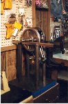
Here is a set of S&S wheels (for a H-D) hung on knife-edges with 'bob' added to male rod to achieve equilibrium.
|
| To Part 6: Assembly |
|
