|
|
|
|
|
|
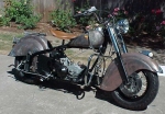
| This project is taking much longer than originally anticipated, due to parts delays, which have virtually stopped all progress for substantial periods of time. I would normally be able to do a ground up resurrection in about 4 or 5 months (using reproduction parts) with minimal down time, assuming you have everything timed properly. In this case, I had a maximum time allowance of 14 months (leaving a 2 month buffer), but even with the engine and brake modifications, I had anticipated about 6 to 8 months. I'm not really running out of time yet, but since I have limited space, it does delay other projects. Once Winter sets in, working the bugs out of the finished product will be slowed dramatically, and since the goal is to complete the Century Ride with with this bike, I want everything to be well proven and trouble free. I'm currently about 6 months into it, with just under 10 months remaining, my 2 month buffer may be all I have left for fine tuning. I left extra time in this project because I am using some very new products, such as Kiwi's new Stainless Steel exhaust system, and their new 80" flywheels, and heavy duty rods. Then there are the Australian aluminum cylinders, which are to be mated to JE forged pistons, of a custom designed pin location. All of these items were in production, but not completed when I started the project. As is usually the case, some fine tuning has been required at the manufacturing level, which has caused several delays in availability, but we're very close now. (8/10 Update: The lower fork legs are in transit to me! YEE HA!) | Click
on pictures for full size
|
| I just took on the KING clutch dealership, and it has kept me side tracked some, but since I have been running the clutch for a few months now, I was too impressed with the product to pass up the opportunity. I set up a web site where the kit can be purchased and there are links to Virtual Indian articles on the development and several other links. If you aren't running the KING clutch, or Duff's MOTOVALVE, you're missing the boat (actually, you're missing smooth shifting and crankcase breathing)! This has been a good diversion which keeps me occupied while I wait for other parts to be manufactured. | 
Click to visit Stan's site |
| The fork legs showed up (8/14) HOOOOORAAAAAAH!
Now I can assemble the forks, and start fitting the fender. Then comes
the disc brake work. Life will be much easier in the shop once this beast
can be rolled around on it's own two wheels. The latest update (8/21) on
the custom pistons, is another 4 weeks! Once the pistons are done and the
rods and flywheels show up, I can begin engine assembly and I'll be able
to start to wrap up some details.
Well, the Tenino meet was a great success for the KING clutches, but I spent more than I took in! There was this 48 Chief engine in a very ugly Japanese frame that caught my attention.... Since my project bike is basically a 50 chassis with a 47 engine, I would have liked to have the late style motor and oil pump, so I had to buy it. Now I have a complete 47 motor and transmission that I may have to build a bobber out of. It also turned out that Frank Woslum had been trying to buy the frame at Tenino, but the seller wouldn't split them, so now Frank has what he needs, and I have most of what I need (I may still need a rigid frame, Frank). |

Click for cost so far |
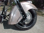
| Okay, I couldn't avoid finishing the fork assembly any longer, so I jumped into it! Having never rebuilt an Indian telescopic fork worked to my advantage. If I had known how much work these things are, I may have avoided it even longer. After several hours of fitting and re-fitting everything, I finally had both legs assembled and on the bike. When I had the axle made, I had the spacer left extra long so I could cut it to fit. Well, The wheel assembly JUST fit between the fork legs, so there won't be much in the way of a spacer when it's all said and done. After surveying the assembly, the brake rotor just clears the fender skirt. The big problem now will be where to locate the caliper... | 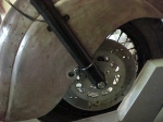
Disc-braked wheel fits neatly |
| Without cutting on the fender, it will
most likely have to mount below, and to the rear of the fender skirt. This
is going to make mounting very difficult at best. If, for some reason this
doesn't work out because of the skirted fender, I always have the original
wheel that could be installed, but that's only a last resort. I've seen
several Indians with front disc brakes, but they have always been on bikes
without full skirted fenders.
You'll probably notice that in the initial fitting of the front wheel, I had the rotor on the left, but it moved to the right later. I had forgotten that I originally set the wheel up to have the rotor on the right, as well as both valve stems, so I switched it to the right side where it belonged.... DOH! I also came up with a unique new tank emblem, let me know what you think of it! :} |
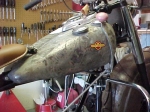
King Chief? Do you need some VI stickers, Stan? :-) Moen |
| I originally planned to use a GMA brake caliper, but then I had the idea to check with the local Jap bike wrecking yard, to see if a late model crotch rocket might use something that I could pick up cheaper than the GMA unit. That turned out to be pretty easy, but they were awful proud of the one I wanted ($100), but still less than half the cost of a new unit. I took it home and fabricated a bracket out of wood, because once I start carving on 6061 aluminum, it gets kind of expensive when you screw up. I ended up making 3 templates before I had one I liked. Then I called around to see where I could get some real heavy plate to build it out of. In this area, there aren't many places to choose from, but I found one place that would sell me some 1/2" plate in the 6" by 14" size I needed. I could have gone up to an inch thick, but 1/2" was as thick as I could find available, and it'll be plenty strong. My goal is to be able to spread the brake load over as much area as possible, since this fork was never designed for a disc system, and when you get a caliper hanging that far from the mount point, things start to get a little hairy. Look at a modern front brake, and you'll see that the caliper is usually mounted on tabs that are cast into the rear of the lower fork slider. This places the force very close to the support member. Now look at where the Chief caliper is located, and you'll start to see why I get concerned about moment arm ratios. Couple that with the fact that all of this is bolted to the fork, instead of being an integral part, and it really gets spooky. Unlike computers, when you have a front brake wrap itself around the fork, fatal error really means FATAL ERROR. I've seen it happen, and believe me, it isn't a nice way to dismount a bike. | 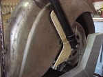
Good idea to make a template for the caliper bracket in wood first |
| After final fit of the brake assembly,
I built another band clamp to surround the fork leg at it's lowest point,
which adds the desired reinforcing (paranoia clamp). I'm using a braided
stainless brake line, which provides the most stable line system, but stainless
lines can act like a hack saw. I always cover stainless lines with heat
shrink which helps keep them from abrading anything they come in contact
with, but it drives most people nuts to cover the expensive lines like
I do. As I've said all along, the goal here is to blend function with form.
The rotor mount holes were only 5/16" while the older style hub used 7/16"
mount bolts, so it required drilling the rotor, and machining a recessed
head on the bolts to match things up properly. Stock rotors are cast, and
they drill easily. After market stainless rotors, are much tougher, but
they don't stop as well either.
After some minor adjusting, the static brake test went extremely well. The caliper engages smoothly, and holds the wheel dead solid. Obviously, I can't do any testing under power at this point, but I expect the results will be very similar. |
Complete disc brake system cost $400, but could be done cheaper (or more expensive) depending on parts used |
| Maybe this project will inspire some of you to add disc brakes to your riders since the total cost of the setup will be around $400. That figure includes the used master cylinder, caliper, wheel assembly, new bearings and seals, axle, bolts, aluminum plate, stainless spokes and stainless line. The total time invested in the system should be around 12-15 hours. Also keep in mind that there were absolutely no modifications to any original Indian parts. All of the modified parts were from donor Harleys or Jap bikes that outlived their original mounts. Besides, it gives all new class to these parts to be mounted on an Indian. You might also say, why is this fool going to so much effort to make this thing more modern? Well, I ride these things. I don't own trailer queens, and this one will be required to meet the demands of daily driving conditions in city traffic without hesitation. In heavy traffic, stopping is more important than anything else the bike can do, so why not make improvements to an otherwise marginal system.... | 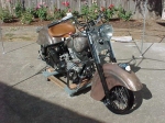
Built to ride! |
| When I met Cotten at Davenport, he showed me the intake seals he made from PEEK (plastic), and he said the bike they were being tested in was just sold, so I volunteered to test them in this project. I'll run a cast iron manifold wit the PEEK seals in this particular case. There is a picture of the seals on a manifold, with a pressure plate mounted for testing. Once the manifold is mounted, and both intake valves are closed, I run a regulated air line to the plate, and pressurize to 10 psi. Then, using a mild soap solution, wet each joint and watch for any bubbles. this will assure a good intake seal, and help eliminate one more potential problem. Once the seals are fully tested, the plan is to purchase a length of the very expensive material, and have them CNC cut in sizes to suit the various Indian and Harley manifolds. Expect retail pricing to be higher than the brass cones, but the advantage will be a positive seal that is reusable. Along these same lines, I bought a set of the high dollar James silicone beaded head and base gaskets to try out on this beast. | 
Manifold with pressure plate and PEEK seals. More info on the seals here |
| Once I painted all the brake parts, I
re-assembled everything, and drilled the remaining fender mounting holes.
With everything on the front end buttoned up, it was time to juice up the
forks. Now, I'm sure that in some obscure Service Shot, or manual that
I don't have, they tell you the preferred method of doing this, but without
this information I was left to my own resources. I used a hand vacuum pump,
which is designed for automotive use, and for brake bleeding. I set the
system up as a syphon pump, where LOW air pressure would draw the oil from
the canister and feed it into the drain hole at the bottom of the fork.
Note that I emphasize LOW pressure! If I just said to use air pressure,
some dork would shoot 100 psi into the system and cover their shop and
bike with oil. If you plan to use the high pressure method, PLEASE have
someone standing by with a camera, 'cause I'd love to see the results!
Once the fluid is in the fork, the trick is to remove the feed tube, and
install the plug without losing most of the oil. If you're quick, this
can (almost) be done without much mess.
Next month, I should be into the power train assembly and installation (I promise). If the JE custom pistons aren't done, I'll use standard 80" units. If the new rods aren't ready, I'll use original rods. I know everyone who has read these articles (all 3 of you) want to see the aluminum cylinders, so I'm going to push the project a bit so I can get to that point. Till next month, ride safe. |
Chief
Project so far:
Part 1
Part 2
Part 3
|