| |
March 2000 Tech Feature | www.virtualindian.org |
| Home / Features / Ace Engine page 2 |
| |
March 2000 Tech Feature | www.virtualindian.org |
| Home / Features / Ace Engine page 2 |
| 1926
Ace - inside the Timing Gear Cover.
This view is with the timing gear cover removed. The small crankshaft mounted gear is in the centre of picture, the large gear to your left drives the camshaft (to which it is keyed), the large magneto idler gear is to your right, and the magneto drive gear is at the top right. Missing in this view is the oil pump and oil-pump drive gear below the crankshaft gear - they are of the same size - the two bolt holes for mounting the oilpump are visible near the base of the enclosure. The cam gear and idler gear have twice
the number of teeth as the crank drive gear, so as to to drive the camshaft
at half-speed for correct valve operation. The small gear on the magneto
driveshaft means that the
In this engine, the magneto drive gear is aluminium, a non-standard fitting (?). This engine has been fitted with an aircraft magneto, and automatic advance ignition timing unit. No DIY ignition timing on this Ace!! Note the traces of Indian Red over the
almost black finish. The original color of the Ace for 1926 was listed
as Rolls Royce Blue. Whether the engine of the 1926 Ace was blue or black
is an interesting question - all the remaining traces of paint appear to
be black - but is any of this the original paint ?? This particular 1926
timing gear cover has a warning stamped into it (picture 5). Whether
this was factory-done is an
Inside the 1926
Ace gearbox.
This view is from behind and underneath the bike - the ONLY access to the gearbox is with the sump cover removed, and possibly with the complete engine removed from the bike. Partly visible in the top of this view is the large (and heavy) 10" clutch. This mounts automotive style on the rear of the crankshaft immediately behind the rear cylinder. The gearbox mainshaft and gears are clamped
into the housing using bearing caps - note the lockwire or split pins on
every nut. The labelled picture points out most interesting features. Second
gear (the middle
|

1926 Ace with timing cover off. Picture 5. Warning! 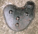
Picture 6. 1926 Ace timing cover. 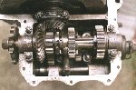
Picture 7. 1926 Ace gearbox. 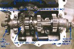
Picture 8. -And with labels! 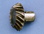
Picture 9. 1926 Ace bevel gear. |